It's when the security light starts flashing that the infamous "chip" in the key becomes a nightmare to many. Gradually the car begins not cranking anymore or if it cranks it would start and die in a second. Randomly it will do this more and more often until it won't start anymore. VATS, PASSkey and Passlock immobilizer systems are killing cars all over North America, they have a short lifespan and are certainly more effective against owners than thieves. Here is how you save your car
1st trick, (if not starting) turn the key forward 2 clicks till right before it would normally start, leave like that for 10 minutes. ( no less ) After 10 minutes, turn key back then forward and your car might start. I did this in my regal for more than a year. If its shuting down while running, im sorry i have no quick fix...
Cheap fix: Bypass the chip in your key. Temporary, but effective. Until the TDM (theft deterrent module) in the dash poops out, then you're kinda screwed. I was told that these types of key security systems have a 7-10 year life span. Sucks for us. This link explains the "Key Issue" pretty well.
----- http://vats.likeabigdog.com/
Never worry again fix: Bypass the whole VATS/Passlock/passkey I or passkey II system entirely. Literally take it out, and throw it away. I just did this in my Regal. Took about an hour. Took longer to find the thing than it did to fix the problem. For a list of cars effected by this problem. See the NEWROCKIES link on the right side of their page......... They sell a unit for 200 bucks to totally bypass this system FOREVER. life time-money back and all that. Finally did this in my car. Well worth the 200 if you've looked into getting this replaced... Anywhere from 600-1000 bucks.
----- http://newrockies.ca?ap_id=judd0081
----- With this fix, you can take that whole Vats, passlock, passkey **** system out of your car all together. Good info on both sites
It works for:
Any GM or Isuzu Vehicle with VATS or PASSKey or PASSLock security systems.
If your car has the chip in the key or in the lock cylinder, then you can save it with this Full Bypass.
Trucks
.
GMC/Chevy
1998-2006 S10/T10/Sonoma
/Blazer/Jimmy
1998-2007 Suburban/Avalanche
/Tahoe/Yukon
1998-2006 Sierra/Silverado
2002-2008 Trailblazer
2003-2006 SSR
1998-2006 C1500/C2500/C3500
1998-2006 K1500/K2500/K3500
2003-2007 Hummer H2
.
Isuzu
1998-2000 Hombre
2005-2006 I280/I350
2007-2008 I290/I370
.
Cars/Vans
.
Isuzu
2003-2007 Ascender
.
Pontiac
1994-2003 Grand Prix
1998-1999 Montana
2006 Torrent
1996-2005 Grand AM
1994-1998 Trans Sports
1988-1999 Bonneville
1988-2002 Firebird
1995-2005 Sunfire
1996-2002 Trans Am
.
Buick
2004-2007 Rainier
1994-2005 Century
1993-2004 Regal
1982-1999 LeSabre
1991-1996 Park Avenue / Ultra
1994-1996 Roadmaster
1991-1996 Roadmaster Estate Wagon
1982-1999 Riviera
1988-1991 Reatta
1996-1998 Skylark
1982-1990 Electra (all models)
.
Oldsmobile
1996-1998 Achieva
1999-2004 Alero
1994-2004 Aurora
1998-2004 Bravada
1991-1993 Delta 88
1994-1999 Eighty-Eight
1991-1996 Nighty-Eight
1998-2002 Intrigue
1990-1992 Toronado
1994-1997 Cutlass Supreme
1997-1999 Cutlass
1997-1999 LSS/Regency
1997-1999 Silhouette
1991-1996 Custom Cruiser
.
Chevrolet/GMC
1998-2005 Astro/Safari
1998-2008 Envoy
2005-2006 Equinox
1998-2007 Savana/Express
1995-2005 Monte Carlo
1997-1999 Venture
1995-2001 Lumina
1988-2002 Camaro
1995-2005 Cavalier
1982-2004 Corvette
1994-1996 Caprice/Caprice Wagon
1995-1996 Impala SS
2000-2005 Impala
1997-2005 Malibu Classic
1997-2003 Malibu
.
Cadillac
1986-1993 Allante
1982-1996 Fleetwood
1985-1996 Fleetwood Brougham
1992-2004 Seville
1992-2004 SLS/STS
1985-1999 Deville
1994-1999 Deville Concours
1997-1999 Deville D'Elegance
1988-2002 ElDorado
1994-2002 ElDorado Touring
1999-2007 Escalade
.
Saturn
2000 LS/LS1/LS2/LW1/LW2
2001-2002 L100/LW100
2001-2003 L200/LW200
2001-2005 L300/LW300
2004-2005 L-Series
2002-2008 VUE
1996-2002 SL/SL1/SL2
1996-2002 SC1/SC2
1996-2002 SW1/SW2

Tuesday, July 26, 2011
Friday, July 22, 2011
how to rewire hazard lights to work with ignition off on
Hazard Lights
The usefullness of hazard lights is obvious and it's disappointing that bike chose not to put them on these bikes. The theory of them is simple, simply have a switch that connects the left and right indicators together and power the flasher unit regardless of the bike's ignition being on. There's a few "black boxes" on the market to put hazard lights on bikes. Most of them're in the US$60 price range, some have funky features like auto-shutdown or "wig wag" lights, but really all you need is something that'll make all your turn signals flash simultaneously, right? There's a few design issues to consider with this system.
- The standard flasher unit's only rated to handle two lamps. If you put four lamps through it (or six if like me you have a trailer) you'll kill it in no time flat. You'll need to replace it with a heavy duty flasher suitable for use with hazard lights. If you have LED's in your indicators you'll need one that's not load sensitive, or you'll need to use load balancers on the LED's.
- The hazard lights need to work when the ignition's off, but simply supplying power to the flasher when the ignition's off will allow power to feed back to the fuse box making various parts of the bike live when they're not supposed to be. Two solutions are to switch the normal power line to the flasher off when the new one's turned on, or to put a diode in the normal power line. I chose the diode as it was a lot simpler than extending wires to reach to the switch.
- Simply connecting the left and right indicators together will stop them working in normal circumstances - ALL of them will flash when you signal left or right. Solution here's similar to the above, two diodes to stop them feeding back to each other when hazard's not selected.
- Bikes aren't waterproof, electricity LIKES water, and most switches aren't sealed. You can either mount the switch in a sealed enclosure which makes for lots of bulk, or use a sealed switch. Jaycar Electronics stocks a suitable unit (part number ST0555) and for extra safety a rubber boot ((ST0590).
- For safety the hazard lights must be fused. You can either run a seperate line to the battery with it's own fuse, or use the connector for the auxilliary power socket which is already fused (assuming you don't already have the aux power socket installed).
- For legal and logical reasons you need a "pilot light" (read idiot light) for the hazard lights. The standard pilot light works by earthing through the opposite side's lamps but if both sides are flashing the pilot won't light. Two more diodes are used here, with both sides connected through them to one side of the lamp, and the other side earthed. You could use a seperate light (eg: an illuminated switch) if you want, if so you don't need to modify the standard one.
What you'll need
- Heavy duty flasher (or Suitable LED flasher). There's several types so be sure you get the right one. This bike requires a three pin flasher, with pins marked 31, 49, and 49A. It also has to be a square one (not round) or it won't fit.
- 5 power diodes, 1N4004 or similar (or 3 if you don't want to modify the idiot light)
- DPST switch (most dual pole switches are also dual throw (DPDT), that's fine - we just ignore the second throw)
- Various consumables eg: a metre or two of suitable gauge hookup wire, solder and iron, heatshrink tubing, PVC tape, zip ties.
- The normal tools (8mm & 12mm spanners, 5mm allen key, wire cutters & strippers etc)
How it works
A flasher unit works by always having power supplied to the unit while the bike's on, and earthing the flasher through the lamps on one side or the other as selected by the indicator switch which causes the selected lamps to light. What our modification does is add a switch that does two things: supplies power to the flasher even when the bike's turned off, and connects both the left and right lamps to the flasher so it earths through all of them at once. It also adds five diodes to do three things: one diode to stop the fusebox being powered when the hazard lights are enabled, two diodes to stop the left and right sides feeding back to each other under normal circumstances, and two diodes to enable the pilot light to work when hazards are enabled. The original and modified circuit diagrams are shown below.

How it's built
Firstly you need to remove the following from your bike: both seats, tank console, fuel tank, wiring cover below front seat, battery box lid and cover (if fitted). The console can remain connected and slung over the handlebars. Remember to place the tank on something soft to avoid damage to the finish (a flattened cardboard box works fine). Located the flasher unit on the right side of the frame as shown below. Unplug it and replace it with your new one. You can turn the ignition on and make sure it works as normal if you like. (Don't start the bike though.)

AT THIS POINT DISCONNECT THE NEGATIVE TERMINAL OF THE BATTERY!
I know bikes instructions tell you to do that when you're doing things like fitting windscreens and sissybars, but on this project we're messing with permanantly live connections so we actually have to do it this time.
The next step is to make up the switch. Below's a pic with the wiring layout for the switch and flasher unit. I'm assuming you're using a DPDT (dual pole dual throw) toggle switch. If you've chosen something else it shouldn't be too hard to interpret. The terminals on the switch probably aren't actually numbered, that's just for our reference. Note that all solder joints are also heatshrinked. Firstly solder about six inches of wire to terminals 1, 4 and 5. If you're using the aux power socket's connector you can crimp on a male spade lug to the end of terminal 4's wire, or if you're connecting to the battery use the inline fuse holder and solder a large ring lug onto the other end to connect to the positive battery terminal. Solder about two inches of wire to terminal 2, then solder the two diodes to the wire be careful about the polarity of the diodes). Solder about 15 inches of wire to the other end of each diode. If you want to add black sleeving to the two long wires and the wires to the flasher unit it makes for a neater installation, but it's not critical. It's also not a bad idea to insulate the unused terminals on the switch with a little heatshrink, melted and crimped at the open end. You might have to add some solder to those terminals to make them large enough for the heatshrink to grip.

Mount the switch in the engine support bracket from the left side. Feed the two wires from terminals 1 and 5 out to the base of the flasher unit, the wire from terminal 4 near the connector or battery, and the two wires from terminal 2 to the wiring harness below the seat. Do not connect power wires at this point. Try to run the wires along existing wires, you can add zip ties to keep them in place but don't fully tighten them yet - you'll want to adjust it all when you're done.
Next, locate the wiring harness below the front seat. You're looking for the harness that feeds the tail light and rear indicators. It has five wires, the colours of which change as they cross the connector. This is the point where we'll be feeding the output from the flasher back into the lights. You can use the wire on either side of the connector, but there's probably more free space on the "taillight side" of the connector. I unplugged it and pulled the harness out from the side of the rear guard, pulled back the black sleeving and cut, soldered and heatshrink'd the extra wires in there, then put it all back. This makes for a nice neat addition without adding extra bulk below the (already full) wiring cover.
"Bike Side" of connector | Taillight side of connector | Purpose |
|---|---|---|
Green/White Trace | Brown | Right Indicator |
Green/Purple Trace | Blue | Brake Light |
Yellow | Red | Tail Light |
Black | Black | Earth |
Green/Red Trace | Orange | Left Indicator |
The next step is to modify the wiring at the flasher. Cut the wire leading to terminal 49 of the flasher about half way along it's free length. Solder the diode (noting its polarity) and the wire from terminal 5 of the switch to the socket, then solder the cut wire to the other end of the diode. Cut the wire from terminal 49A and splice in the wire from terminal 1 on the switch. You can now plug the power line into the socket (or onto the battery terminal as per your installation method). Connect the negative terminal of the battery and switch your hazard lights on. If it is all correct you should see all 4 lights flashing merrily away, however the pilot light won't be working at this point.. If they don't, or if you see smoke, you should disconnect it immediatley and retrace all your connections. Pay particular attention to the orientation of the diodes, as having them backwards will stop the working. (They can simply be turned around if you've put them in backwards, they won't be damaged.)
In the tank console locate the indicator pilot light, and cut both wires to it about half way along their free length. Solder a diode to each of these wires, then solder both diodes to one of the wires in the pilot light. Locate the (black) earth wire for the tacho/clock connector. Splice a wire into it, then solder that wire to the free wire on the pilot light. Insulate all connections as usual. Note: The wiring that bike have used in the tank console's wiring harness is of a type that doesn't take well to solder. It CAN be done by scratching the enamel off the individual strands and making sure the soldered joint is VERY hot, but it's a lot easier in this area to use "scotchlock" joiners or similar. Obviously this won't work with the diodes, however you can solder a short piece of normal wire to the diode then scotchlock that wire into the harness. I'm not happy with this method and am working on replacing the entire console harness with something a little more user-friendly, since I've made many modifications to this area and it's starting to get a little untidy. The picture below shows the diodes and eath connected to the back of the pilot light. Note the orientation of the diodes.
.
Test the hazard lights. All four corners should flash with the ignition on OR off, and the indicator switch in any position. The pilot light should also flash with both the hazards and indicators. If all's as it should be, reassemble your bike.
Monday, July 18, 2011
how to remove the water tube from ge profile freezer door
One of the most costly and aggravating repairs that you may run into in your GE Arctica or Profile refrigerator is a leaking water line inside the freezer door. This waterline is a plastic tube that is foamed in place inside the door. The tube may split or crack or in some other way become damaged and start leaking, leaving a puddle of water underneath the door. At this point, you have two choices:
1. Replace the entire door at a cost exceeding $200, or
2. Implement the repair procedure illustrated in this fine pictorial essay for a cost of about $20.
To go for repairing the leaking water tube repair, click the link below and follow the procedure:---
http://www.scribd.com/doc/38608714/GE-Refrigerator-Door-Water-Tube-Repair
----------
If the instructions are not readable and diagram is very small to see.Then at the lower side there is plus and minus sign.To increase and decrease the page size.Click the plus side to make the view bigger.
where is the fuse for transmission control module located on 93 subaru legacy.
It's on the left side dash , but it's actually bolted high up on the firewall. Stick your head down to were the base of the gas/break pedal area, and look up. It's a metal (look at the first post in the reverse engineering thread) and it may have a a few relays attached to the bottom of it.
look at the wiring diagrams and diagnostic sections for this page:
----------------
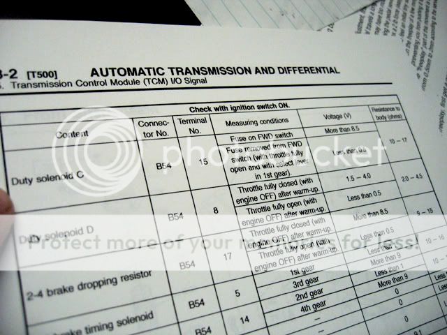
Over on the far right we see that the solenoid presents between 10-17 ohms of resistance.

Consequently, this is the number that the TCM expects to see when the solenoid is functioning properly. Above or below that number by too much and the TCM will throw a fault code.
Consequently, this is the number that the TCM expects to see when the solenoid is functioning properly. Above or below that number by too much and the TCM will throw a fault code.
--------------
track down the wire that carries the TCM signal to the solenoid. Back to the FSM:
We're looking for the AWD transfer solenoid which is called the "Duty Solenoid C" in my manual. As you can see, it can be found at terminal 15 of connector B54

Looking at the layout of the B54 connector, we see the physical location of pin 15

So, where exactly is this connector located in the car? Well, it's on the TCM. Which you'll find mounted just to the left of the steering column. Crawl into the driver's side footwell and look up, you'll see it. Here are some pics to give you an idea of what you're looking for. Note the orientation of the brake pedal to get your bearings


We're looking for the AWD transfer solenoid which is called the "Duty Solenoid C" in my manual. As you can see, it can be found at terminal 15 of connector B54
Looking at the layout of the B54 connector, we see the physical location of pin 15
So, where exactly is this connector located in the car? Well, it's on the TCM. Which you'll find mounted just to the left of the steering column. Crawl into the driver's side footwell and look up, you'll see it. Here are some pics to give you an idea of what you're looking for. Note the orientation of the brake pedal to get your bearings
---------------
Ok - so the connector we're interested in is the white one (located closest to the firewall). We've seen the location of the wire on the connector diagram of B54.
According to the tests procedures - we need to install the FWD fuse and turn the ignition to "on". The FWD fuse is located in the engine compartment fuseblock.
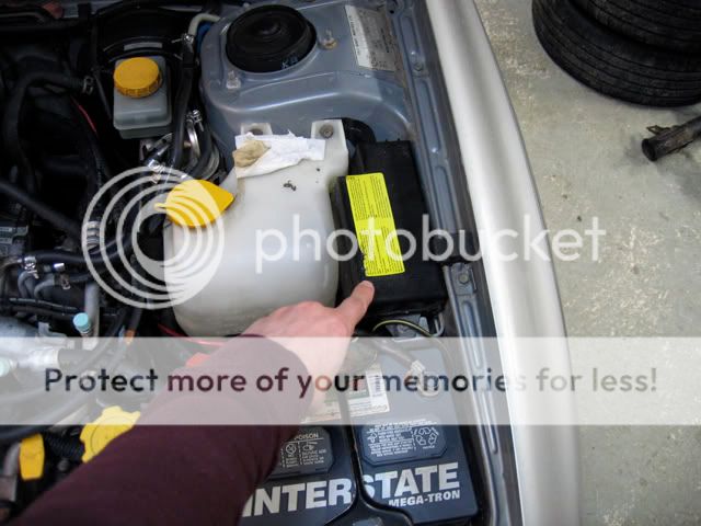
Remove the lid and locate the FWD fuse position
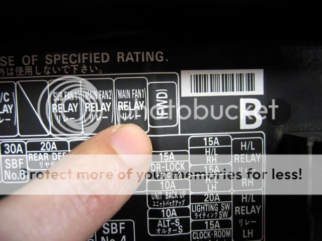
The fuse probably goes here:

According to the tests procedures - we need to install the FWD fuse and turn the ignition to "on". The FWD fuse is located in the engine compartment fuseblock.
Remove the lid and locate the FWD fuse position
The fuse probably goes here:
Thursday, July 14, 2011
how to adjust push pull throttle on honda crf-230
Getting to the carb and changing jets can be intimidating, especially if you're stumped by a "normal" carb. The Honda is incredibly complicated and even has a dual cable push/pull throttle. You can get to the carb without removing it, but we found it much easier to do the changes with carb off the bike, nice and free.


In order to have easy access to the carb, remove the gas tank, seat and side panels
-----------------
This cable should be removed. Honda uses two cables on the carb. One pulls and one pushes
--------------
This cable should be retained. Loosen the jam nuts and slip the cable out of the way
-------------
The locking nut on the throttle housing must be loosened in order to remove the push cable
----------------
Remove the push cable from the throttle housing
--------------
The remaining throttle cable should detached from the linkage
------------
Also click both this links below for more help:---
-------------
The another link:---
Wednesday, July 13, 2011
vacuum line diagram for 81 380sl mercedes
There are vacuum line diagrams available for 81 380sl mercedes
First click this link below and see the pdf diagram:---
| 380SL%20Intake%20Vacuum%20Parts[1].pdf (25.5 KB. |
where the red vacuum line that goes thru the firewall on the drivers side goes to
red green is for your climate control. I will attach a vacuum diagram.
red green is for your climate control. I will attach a vacuum diagram.
------------------------------

The shaded line is your red green vacuum supply line. It also goes to the vacuum storage tank.
Image Reference :
13 Switchover valve for defroster nozzle flaps (short stroke) and center nozzle flap
14 Switchover valve for legroom flaps
15 Switchover valve for defroster nozzle flaps (long stroke)
16 Switchover valve for vacuum elements of main air flaps
35 Vacuum connection on intake manifold
36 Check valve
37 Vacuum reservoir
38 Vacuum element for defroster nozzle flaps (flaps "open")
39 Vacuum element for legroom flaps (flaps "closed")
4Oa Vacuum element for center nozzle flap (flap "closed")
42 Vacuum element for main air flap left (flap "closed", W/ 20% fresh air)
43 Vacuum element for main air flap right (flap "closed", W/ 20% fresh air)
44 Throttle (orifice)
45 Check valve
48 5-point distributor
49 4-point distributor
50 3-point distributor
Color Code Of Vacuum Lines :
bl = blue
drt = dark red
ge= yellow
gn = green
gr = grey
hbl = light blue
rt = red
sw = black
ws = white
The same diagram from above for more clear view:---
------------------
Tuesday, July 12, 2011
how to remove console on GMC Car?
The upper bezel is the trim plate at the top of the console. It snaps in place. Wrap the tip of a flat screwdriver in tape and use it to pry the trim free. The tape will prevent scratching the panel.


GMC Envoy 02-05 Stereo Removal
Step 1: Engage parking brake.

GMC Envoy 02-05 Stereo Removal
Step 2: Remove screw in cupholder.

GMC Envoy 02-05 Stereo Removal
Step 3: Remove screws from front center of console.

GMC Envoy 02-05 Stereo Removal
Step 4: Remove rubber tray and screws from rear of console.

GMC Envoy 02-05 Stereo Removal
Step 5: Remove rubber mat from bottom of center console. Remove screws.

GMC Envoy 02-05 Stereo Removal
Step 6: Remove the center console tray piece and remove screws below. Pull entire center console towards rear of vehicle.

GMC Envoy 02-05 Stereo Removal
Step 7: Remove screws from both sides of carpeted panel below radio. Remove the carpeted panel.

GMC Envoy 02-05 Stereo Removal
Step 8: Remove 2 screws at botton of radio trim bezel.

GMC Envoy 02-05 Stereo Removal
Step 9: Unclip radio trim bezel.

GMC Envoy 02-05 Stereo Removal
Step 10: Remove screws and plugs from radio.

GMC Envoy 02-05 Stereo Removal
------------
more instructions:---

GMC Canyon 04-09 Stereo Removal
Step 1: Unclip trim around radio.

GMC Canyon 04-09 Stereo Removal
Step 2: Remove 3 7mm bolts securing radio to vehicle.

GMC Canyon 04-09 Stereo Removal

Tip
Front floor console
----------------------
Bezel Assembly
- Use a flat-bladed plastic trim tool to release the retainer clips along the rear edge of the bezel.
- Lift the bezel out of the console assembly.
- If replacing the front floor console bezel assembly, transfer all necessary components.
----------------------
REMOVAL PROCEDURE
IMPORTANT: Do not grab or pull on the CD storage door when removing the trim bezel.
Remove the screws securing the trim bezel to the console extension.
Protect the console extension from damage then carefully use a small prying device to push in the tabs underneath the trim bezel securing the top of the trim bezel.
Remove the trim bezel.
To remove the bezel on the luxury console, refer to Bezel Replacement - Floor Console (Luxury) in Instrument Panel, Gages and Console.
Use a small screwdriver in order to release the CD player retainers.
Slide the CD player out.
Disconnect the electrical connector.
INSTALLATION PROCEDURE
Connect the electrical connector.
Install the CD player.
When the CD player is fully seated, snap the unit into the retainers.
To install the bezel on the luxury console, refer to Bezel Replacement - Floor Console (Luxury) in Instrument Panel, Gages and Console.
NOTE: Refer to Fastener Notice in Service Precautions.
Install the trim bezel and the screws.
Tighten
Tighten the screws to 2 N.m (18 lb in ).
----------------------
Open the rear cup holder on the console and pull it out all the way. Then open up the lid to the console.
Grab on either side of the center pocket of the console and lift it up with your hands. It's held in place by gravity and friction, so it should be fairly easy to lift out of place.
Locate the four bolts that hold the console to the floor. They're in both the front and back of the console, right in the middle on metal braces.
Unbolt the console from the floor using the 3/8-inch ratchet, extension and sockets. You may have to alternate between using the extension and not, depending on how far you can reach your arm.
Lift the console out of the vehicle and place it to the side.
----------
For center console removal:---
Disable the Airbag, or SRS System
Turn the steering wheel so the wheels are facing straight ahead. Turn the ignition to the Lock position and remove the key.
Remove the fuse cover from the end of the instrument panel on the driver's side. Consult the legend on the cover and remove the fuse that protects the airbag circuit. Wait at least two minutes while the system depletes the back-up power supply.
Remove the screws that secure the driver's knee bolster with a Phillips screwdriver and pull it away from the dash. Pull the driver's airbag electrical connector out of the terminal at the steering column.
Open the glove box and pull the passenger airbag electrical connector out of the terminal.
Remove the Seats
Slide the driver's seat all the way forward on its runner. Locate the floor-to-rail bolts on each side of the runner and remove them with a socket wrench.
Slide the seat all the way backwards on the runner and remove the rear floor-to-rail bolts in the same way.
Lift the seat up and remove it from the vehicle.
Repeat the procedure with the passenger seat and remove it from the vehicle.
Remove the Center Console
Locate the mounting bolts on the four corners of the console support.
Remove the bolts with a socket wrench.
Lift the console up and out of the vehicle.
To reinstall the seats, follow the steps for removal in reverse order.
Subscribe to:
Posts (Atom)